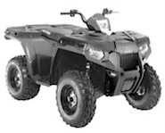
2012 Sportsman 400/500 and EFI Tractor Service Manual - 9923412
Polaris Sportsman ATV service manual for used by professional Polaris repair shops.
Manual Part Number: 9923412
Models covered in this manual:
- 2012 Sportsman 400 H.O.
MODEL NUMBER: A12MH46AX, AZ, AF
ENGINE MODEL: EH460PLE050 - 2012 Sportsman 500 H.O.
MODEL NUMBER: A12MH50AX, AZ, AD, AQ, FF, FY, FX
ENGINE MODEL: EH500PLE13B - 2012 Sportsman Touring 500 HO
MODEL NUMBER: A12DH50AX, AZ
ENGINE MODEL: EH500PLE13B - 2012 Sportsman Forest Tractor 500 EFI Specifications
MODEL NUMBER: A12MN50ET, EX
ENGINE MODEL: EH500PLE216
Manual chapters:
CHAPTER 1 - GENERAL INFORMATION
CHAPTER 2 - MAINTENANCE
CHAPTER 3 - ENGINE
CHAPTER 4 - FUEL SYSTEMS, CARBURATION, EFI
CHAPTER 5 - BODY / STEERING / SUSPENSION
CHAPTER 6 - CLUTCHING
CHAPTER 7 - FINAL DRIVE
CHAPTER 8 - TRANSMISSION
CHAPTER 9 - BRAKES
CHAPTER 10 - ELECTRICAL
2012 Polaris Sportsman 400 Service Manual Wiring Diagram
Manual PDF file is indexed and searchable. Manual includes hi-resolution images and diagrams.


To find information in PDF file please use "Ctrl+F" or "Command+F" for Mac and enter keywords you need to find in a manual.
File will be available for download in minutes!
 "2012 Sportsman 400/500 and EFI Tractor Service Manual - 9923412" manual can be saved to any computer hard drive, flash storage, burned to a CD or DVD ROM or any other digital media.
This Manual PDF file is:
- + Printable: Yes
- + Viewable on: MS Windows, Mac, Android, iOS, Linux
- + Requires: Adobe Acrobat/Preview
Once manual is downloaded any number of pages could be printed or it could be printed in whole.
Manual could be opened in Adobe Acrobat on any mobile device (like iPad, iPhone or Android device etc.) any computer capable of viewing a PDF files including IBM compatible computers running Windows, Linux (or any other flavor of UNIX). Apple Computers have native support for PDF files.
Write a Review
Full list of manual chapters:
CHAPTER INDEX
CHAPTER 1 - GENERAL INFORMATION
MODEL NUMBER INFORMATION
Model Number
Vehicle Identification Number (VIN)
Engine Designation Numbers
Vehicle and Engine Serial Numbers
Transmission I.D. Location
Publication Part Numbers
Vehicle Specifications
2012 Sportsman 400 H.O.
2012 Sportsman 500 H.O.
2012 Sportsman Touring 500 HO
2012 Sportsman Forest Tractor 500 EFI Specifications MODEL NUMBER: A12MN50ET, EX
MISC. NUMBERS/CHARTS
Conversion Table
Standard Bolt Torque Specification
Metric Bolt Torque Specification
SAE Tap Drill Sizes
Metric Tap Drill Sizes
Decimal Equivalents
Paint Codes
Replacement Keys
Glossary Of Terms
CHAPTER 2 - MAINTENANCE
SPECIAL TOOLS
MAINTENANCE
Periodic Maintenance Chart
Maintenance Chart Key
Periodic Maintenance Chart
LUBRICANTS / SERVICE PRODUCTS
Polaris Lubricants, Maintenance and Service Products
LUBRICATION / FLUIDS
Pre-Ride / Daily Inspection
Lubrication Components
Front Gearcase Lubrication
Transmission Lubrication
ADC SYSTEM (IF EQUIPPED)
ADC System Fluid Reservoir Location
ADC Differential Hydraulic Circuit Fluid Change
VEHICLE INSPECTION
Shift Link Rod Inspection
Throttle Inspection
Throttle Cable / Electronic Throttle Control (ETC Switch) Adjustment
Fuel System
Fuel Lines
Vent Lines
Choke (Enricher) Adjustment - (500 Carb)
Compression Test
Engine Mounts
Spark Plug
Battery Maintenance
Liquid Cooling System Overview
Coolant Strength / Type
Cooling System Hoses
Radiator/Grill Screen
Cooling System Pressure Test
Coolant Level Inspection
Radiator Coolant Level
Air Filter/Pre-Filter Service
Air Box Sediment Tube
Breather Filter Inspection
Breather Hose
Recoil Housing
Engine Oil Level
Oil and Filter Change
Oil Pump Priming Procedure
Valve Clearance
Intake Valve Clearance Adjustment
Exhaust Valve Clearance Adjustment
Steering
Tie Rod End/Steering Inspection
Camber and Caster
Wheel Alignment
Toe Alignment Adjustment
Exhaust Pipe
Brake System Inspection
Brake Pad Inspection
Hose/Fitting Inspection
Auxiliary Brake Testing
Auxiliary Brake Adjustment (Hydraulic)
Suspension Spring Preload Adjustment
Front Suspension
CV Shaft Boot Inspection
Controls
Wheels
Wheel, Hub, And Spindle Torque Table
Wheel Removal Front or Rear
Wheel Installation
Tire Pressure
Tire Inspection
Frame, Nuts, Bolts, Fasteners
CARBURETOR MAINTENANCE
Choke (Enricher) Adjustment (Non EFI)
Pilot Screw
Pilot Screw Adjustment
Idle Speed Adjustment (Non EFI)
Fuel Filter (Non EFI)
Carburetor Draining
Maintenance Schedule
CHAPTER 3 - ENGINE
SPECIFICATIONS
Torque Specifications
Engine Fastener Torque Patterns
Sportsman 500 H.O. Engine Service Data (EH50PLE 498cc Fuel Injected and Carbureted)
Sportsman 500 H.O. Engine Service Data (EH50PLE 498cc Fuel Injected and Carbureted)
Sportsman 400 H.O. Engine Service Data (EH46PLE 455cc Carbureted)
Sportsman 400 H.O. Engine Service Data (EH46PLE 455cc Carbureted)
SPECIAL TOOLS
GENERAL ENGINE SERVICE
Cooling System Specifications
Cooling System
Accessible Components
Engine Removal
Engine Installation Notes
Cylinder Hone Selection/ Honing Procedure
Honing To Oversize
Cleaning the Cylinder After Honing
Crankshaft Straightening
Engine Lubrication
Oil Pressure Test
Oil Flow
Oil Flow Diagram
Engine Exploded Views
ENGINE DISASSEMBLY
Cam Chain Tensioner / Rocker Arm / Camshaft Removal
Cam Chain Tensioner Inspection
Rocker Arm / Shaft Inspection
Camshaft Removal
Automatic Compression Release Removal / Inspection
Automatic Compression Release Installation
Camshaft Inspection
Cylinder Head Removal
Cylinder Head Exploded View
Cylinder Head Inspection
Cylinder Head Warpage
Cylinder Head Disassembly
Valve Inspection
Combustion Chamber
Valve Seat Reconditioning
Cylinder Head Assembly
Valve Sealing Test
Valve Clearance Adjustment
Cylinder / Piston Removal and Inspection
Piston Removal
Cylinder Inspection
Cylinder Hone Selection / Honing Procedure
Honing to Oversize
Cleaning the Cylinder After Honing
Piston-to-Cylinder Clearance
Piston / Rod Inspection
Piston Identification
Piston Ring Installed Gap
Crankcase Disassembly
Starter Drive Removal / Inspection
Flywheel and Stator Removal / Inspection
Cam Chain / Tensioner Blade
One Way Valve
Crankcase Separation
Oil Pump Removal / Inspection
Oil Pump Assembly
Counter Balancer Shaft Removal / Inspection
Crankshaft Removal / Inspection
Crankcase Bearing Inspection
Oil Seal / Mechanical Seal Removal (Engine Disassembled)
Crankcase Inspection
Bearing Installation
End Play Inspection / Adjustment
Crankshaft End Play Adjustment
Counter Balancer Shaft End Play Adjustment
Oil Pump Shaft End Play Adjustment
ENGINE REASSEMBLY
Pump Shaft Oil Seal Installation
Crankshaft / Counter Balance / Oil Pump Installation
Crankcase Assembly
Water Pump Mechanical Seal Installation
Water Pump Mechanical Seal Removal (Engine Installed)
One Way Valve Installation
Cam Chain Drive Sprocket Installation
Tensioner Blade Installation
Piston Ring Installation
Piston Installation
Cylinder Installation
Cylinder Head Installation
Cam Chain / Camshaft Installation
Camshaft Timing
Camshaft Timing Illustration
Cam Chain Tensioner Installation
Stator, Flywheel and Starter Drive Installation
Rocker Shaft / Rocker Arm Assembly Installation
Thermostat Installation
Oil Pipes
Oil Pump Priming Procedure
RECOIL (Accessory)
Recoil Disassembly/Inspection
Recoil Assembly
TROUBLESHOOTING
Spark Plug Fouling
Engine
Cooling System
CHAPTER 4 - FUEL SYSTEMS
CHAPTER 4 - CARBURATION
General Information and Specifications
Carburetor Jetting
Mikuni Jet Part Numbers
Special Tools
Carburetion
BST 40 Carburetor Exploded View 1 of 2
BST 40 Carburetor Exploded View 2 of 2
CV Carburetor System Function
Mikuni CV Carb Operation
Carburetor Venting
Starter System (Choke or Enrichment)
Pilot (Idle and Slow) System
Main System
Float System
Pilot Screw
Air/Fuel Mixture Ratio
Jet Needle
Needle Jet
Throttle Opening vs. Fuel Flow
Carburetor Disassembly – Mikuni CV
Carburetor Cleaning
Carburetor Inspection
Carburetor Assembly
Float Height Adjustment
Needle and Seat Leakage Test
Fuel Level Test
CARBUTATED Fuel Tank / Fuel Delivery System
Fuel System Exploded View
Fuel Pump (CARBURATED)
Fuel Filter Replacement (Carbureted)
FUEL GAUGE SENDING UNIT TEST
Fuel Sending Unit Test
Fuel PICK-UP / Sending Unit Replacement (CARB.)
Fuel Pick-up / Sending Unit Replacement
Fuel Tank Vent Routing (non INTL)
Fuel Tank Vent Hose Routing
500 H.O. INTERNATIONAL EMISSIONS SYSTEM
Overview
Troubleshooting
Fuel Starvation/Lean Mixture
CHAPTER 4 - EFI
SPECIAL TOOLS
Part Numbers / Descriptions
500 EFI TRACTOR SPEED CONTROL
System Operation Overview
Air Control Body Removal and Disassembly
Air Control Body Assembly and Installation
Air Solenoid Valve Test / Replacement
Exhaust System
EFI SERVICE NOTES
General Service Information
EFI SYSTEM EXPLODED VIEW
EFI SYSTEM
Component Locations/Identification
FUEL SYSTEM AND FUEL TANK
Fuel System and Fuel Tank Exploded View
ELECTRONIC FUEL INJECTION
General Information
EFI Operation Overview
Initial Priming / Starting Procedure
FUEL LINES
Quick Connect Removal/Installation
ELECTRONIC CONTROL UNIT (ECU)
Operation Overview
ECU Replacement
ECU Service
FUEL PUMP ASSEMBLY
Operation / Testing
FUEL PUMP TEST
Fuel Tank Replacement
Fuel Sending Unit Test
Fuel Pump Replacement
FUEL PRESSURE REGULATOR
General Information
FUEL FILTER
General Information
FUEL INJECTOR
General Information
CRANKSHAFT POSITION SENSOR (CPS)
General Information
MANIFOLD AIR PRESSURE SENSOR (MAP)
Operation Overview
Map Sensor Test
Map Sensor Replacement
INTAKE AIR TEMPERATURE SENSOR (IAT)
Operation Overview
Intake Air Temperature Sensor Test
Intake Air Temperature Sensor Replacement
I DLE AIR CONTROL (IAC)
General Information
THROTTLE POSITION SENSOR (TPS)
Operation Overview
Throttle Position Sensor Test
Throttle Position Sensor Replacement
Throttle Position Sensor Initialization
ENGINE TEMPERATURE SENSOR
General Information
Engine Temperature Sensor Test
Engine Temperature Sensor Replacement
FUEL SYSTEM TROUBLESHOOTING
FUEL STARVATION / LEAN MIXTURE
EFI DIAGNOSTICS USING 'BLINK CODES'
Blink Codes - Operation
DIGITAL WRENCH OPERATION
Digital Wrench Diagnostic Software Overview
Special Tools (also refer to page 3.2)
Diagnostic Software Version
ECU Replacement
Guided Diagnostic Available
Digital Wrench Communication Errors
Digital Wrench - Diagnostic Connector
Digital Wrench Version and Update ID
Digital Wrench Updates
Digital Wrench Serial Number Location
Digital Wrench Feature Map
Engine Controller Reprogramming (Reflash)
TROUBLESHOOTING DIAGRAMS
EFI CIRCUIT - Power On
EFI CIRCUIT - Crank Position Sensor
EFI CIRCUIT - Fuel Pump
EFI CIRCUIT - Ignition Coil
EFI CIRCUIT - Idle Air Control
EFI CIRCUIT - Throttle Position Sensor
EFI CIRCUIT - Manifold Absolute Pressure Sensor
EFI CIRCUIT - Engine Coolant Temperature
EFI CIRCUIT - Air Temperature Sensor
EFI CIRCUIT - Malfunction Indicator Light
CHAPTER 5 - BODY / STEERING / SUSPENSION
GENERAL INFORMATION
Torque Specifications
Special Tools
Decal Replacement
Plastic Insert Removal / Installation
BODY
Side Panel Removal
Front Storage Box Lid / Front Rack and Access Panel Removal / Installation
Foot Well Removal / Installation
Front Bumper Removal / Installation
Mud Guard Removal / Installation
Front Fender Removal/Installation
Front Rack / Storage Box Lid Assembly
Front Cab Assembly
Front Bumper Assembly
Rear Rack Assembly
Rear Cab And Seat Assembly
Rear Storage Box Assembly
Winch and Front Bumper Mounting
Headlight Pod Exploded View
500 EFI TRACTOR SEAT ASSEMBLY
Overview
Seat Dampener Repair
Seat Pivot Repair
500 EFI Tractor Seat Assembly Exploded View
500 EFI TRACTOR STEERING POST AND LOCK
Steering Assembly Exploded View
STEERING
Handlebar Block Installation Procedure
Steering / A-arm Exploded View
A-Arm Replacement
Ball Joint Replacement
Steering Post Removal
Steering Post Assembly
SUSPENSION
Front Strut Cartridge Replacement
Strut Assembly
Sportsman Rear Suspension Assembly
Torsion Bar Exploded View
CHAPTER 6 - CLUTCHING
CHAPTER 7 - FINAL DRIVE
CHAPTER 8 - TRANSMISSION
CHAPTER 9 - BRAKES
CHAPTER 10 - ELECTRICAL
2012 Polaris Sportsman 400 Service Manual Wiring Diagram


